

Описание
Altium — Model Context Protocol server
README
TLDR: Use Claude to control or ask questions about your Altium project. This is a Model Context Protocol (MCP) server that provides an interface to interact with Altium Designer through Python. The server allows for querying and manipulation of PCB designs programmatically.
NEW: Distributor Integration Check component availability, get real-time pricing, find alternatives, and validate your BOM using Nexar API integration. Setup Guide | Features | Workflows
NEW in Phase 5: Board initialization and routing tools! Set board size, add outlines and mounting holes, route traces, place vias, and create copper pours. See Board & Routing Tools section below.
NEW in Phase 4: Component placement has been completely redesigned and now works reliably! See Component Operations section below.
NEW in Phase 2: Project management and library search tools! Create projects, search components across libraries, and manage your workflow. See Project & Library Management section below.
Example commands
- Distributor integration: "Check component availability for my BOM" | "Find alternatives for U3" | "What's the price for 100 units?"
- Run all output jobs
- Create a symbol for the part in the attached datasheet and use the currently open symbol as a reference example.
- Create a schematic symbol from the attached MPM3650 switching regulator datasheet and make sure to strictly follow the symbol placement rules. (Note: Need to open a schematic library. Uses
C:\AltiumMCP\symbol_placement_rules.txtdescription as pin placement rules. Please modify for your own preferences.) - Duplicate my selected layout. (Will prompt user to now select destination components. Supports Component, Track, Arc, Via, Polygon, & Region)
- Show all my inner layers. Show the top and bottom layer. Turn off solder paste.
- Get me all parts on my design made by Molex
- Give me the description and part number of U4
- Place the selected parts on my pcb with best practices for a switching regulator. Note: It tries, but does terrible placement. Hopefully I can find a way to improve this.
- Give me a list of all IC designators in my design
- Get me all length matching rules
Installing the MCP Server
- Make sure Claude has Python 3.11 installed:
drop down > File > Settings > Extensions > Advanced > Python: 3.11.0. If not, install 3.11 and add python to PATH. - Download the
altium-mcp.dxtdesktop extension file from releases - In Claude Desktop on Windows:
drop down > File > Settings > Extensions > Advanced > Install Extension...Select the .dxt file
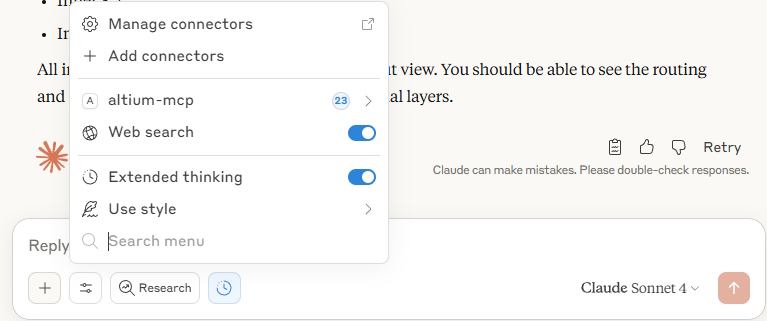
You shouldn't need to restart Claude and you should now see altium-mcp in the tool menu near the search bar.
Creating a new .dxt (For Developers)
pip server/lib (Recommended)
- Populate the packages in the
server/libdirectory: from root dir >python -m pip install --no-cache-dir --target server/lib -r requirements.txt - Update the manifest for
server/liband include any new tools that have been added, bump the revisions, etc.
"server": {
    "type": "python",
    "entry_point": "server/main.py",
    "mcp_config": {
      "command": "python",
      "args": ["${__dirname}/server/main.py"],
	  "env": {
		"PYTHONPATH": "${__dirname}/server/lib"
	  }
    }
  }
- Download Node.js, install Anthropic's DXT tool:
npm install -g @anthropic-ai/dxt, package dxt:dxt pack
uv server/venv (Not Recommended)
On Windows
1.
powershell -c "irm https://astral.sh/uv/install.ps1 | iex"
and then
set Path=C:\Users\nntra\.local\bin;%Path%
- Create the venv directory where DXT expects: from the root directory run
uv venv server/venv --relocatable - Install dependencies to venv:
uv pip install --python server/venv/Scripts/python.exe -r requirements.txt - Update the manifest for
server/venvand include any new tools that have been added, bump the revisions, etc.
  "server": {
    "type": "python",
    "entry_point": "server/main.py",
    "mcp_config": {
      "command": "${__dirname}/server/venv/Scripts/python.exe",
      "args": ["${__dirname}/server/main.py"],
	  "env": {
		"PYTHONPATH": "${__dirname}/server/venv"
	  }
    }
  }
- Download Node.js, install Anthropic's DXT tool:
npm install -g @anthropic-ai/dxt, package dxt:dxt pack
DXT Resources
- Desktop Extensions
- Desktop Extensions Github
- Getting Started with DXT
- Python DXT Example Code
- DXT Manifest
Configuration
When launching claude for the first time, the server will automatically try to locate your Altium Designer installation. It will search for all directories that start with C:\Program Files\Altium\AD* and use the one with the largest revision number. If it cannot find any, you will be prompted to select the Altium executable (X2.EXE) manually when you first run the server. Altium's DelphiScript scripting is used to create an API between the mcp server and Altium.
Available Tools
The server provides several tools to interact with Altium Designer:
Distributor Integration (NEW!)
Real-time component availability, pricing, and BOM validation powered by Nexar API.
Quick Start: API Setup Guide - Get your free Nexar API keys in 5 minutes!
Available Tools:
check_component_availability: Check stock levels across multiple distributorsget_component_pricing: Get current pricing with quantity breaksfind_component_alternatives: Find drop-in replacements for unavailable partsvalidate_bom: Comprehensive BOM validation for production readinesssearch_distributor_parts: Search for components by specifications
Example Usage:
"Check availability for all components in my BOM"
"What's the price for 100 units of manufacturer part LM358N?"
"Component U5 is out of stock. Find me alternatives."
"Validate my BOM for a production run of 50 boards"
"Find 0805 10k resistors with 1% tolerance in stock"
Key Features:
- Real-time stock levels from Digi-Key, Mouser, Newark, Arrow, and more
- Quantity break pricing for cost optimization
- Intelligent alternative part recommendations
- Lifecycle and obsolescence warnings
- Lead time tracking for production planning
Learn More:
Output Jobs
get_output_job_containers: Using currently open .OutJob file, reads all available output containersrun_output_jobs: Pass a list of output job container names from the currently open .OutJob to run any number of them..OutJobmust be the currently focused document.
Component Information
get_all_designators: Get a list of all component designators in the current boardget_all_component_property_names: Get a list of all available component property namesget_component_property_values: Get the values of a specific property for all componentsget_component_data: Get detailed data for specific components by designatorget_component_pins: Get pin information for specified components
Component Operations (Phase 4 - NEW!)
Enhanced component placement and manipulation tools with proper footprint library integration:
place_component: Place a single component on the PCB with specified footprint and position- Automatically searches all loaded libraries for the footprint
- Supports layer selection (top/bottom), rotation, and precise positioning in mm
- Example:
place_component("R1", "0805", 10.0, 20.0, 0, 90)
place_component_array: Place multiple components in a grid pattern with automatic designator numbering- Perfect for placing resistor or capacitor arrays
- Configurable rows, columns, and spacing in both X and Y directions
- Example: Place a 2x3 grid of 0805 resistors with 5mm spacing
align_components: Align multiple components to a common edge (left/right/top/bottom)- Select components to align with comma-separated designators
- Useful for organizing components in neat rows or columns
- Example:
align_components("R1,R2,R3", "left")
delete_component: Remove a component from the PCB by designator- Clean removal with proper PCB update
- Example:
delete_component("R1")
What's Fixed:
- Component placement now properly searches footprint libraries instead of failing
- Footprint primitives (pads, tracks, silkscreen) are correctly copied to the component
- Components are properly registered with the PCB board for full functionality
- All operations use PCBServer PreProcess/PostProcess for atomic updates
Example Workflow:
1. "Place an 0805 resistor at position 50,50mm with 90 degree rotation"
2. "Create a 4x4 array of 0603 capacitors starting at 10,10mm with 5mm spacing"
3. "Align all the components R1, R2, R3, R4 to the left edge"
4. "Delete the test component R_TEST"
Board & Routing Tools (Phase 5 - NEW!)
Board initialization and manual routing capabilities:
Board Initialization Tools
set_board_size: Set the dimensions of the PCB board- Specify width and height in millimeters
- Example:
set_board_size(100, 80)for a 100mm x 80mm board
add_board_outline: Add a rectangular board outline to the PCB- Define outline position (x, y) and dimensions (width, height) in mm
- Creates outline on KeepOut layer with 0.2mm width
- Example:
add_board_outline(0, 0, 100, 80)for a board outline at origin
add_mounting_hole: Add a mounting hole to the PCB- Specify position (x, y), hole diameter, and optional pad diameter in mm
- Creates plated through-hole pad for mechanical mounting
- Pad diameter defaults to 2x hole diameter if not specified
- Example:
add_mounting_hole(10, 10, 3.2, 6.4)for M3 mounting hole
add_board_text: Add text to the PCB- Place text at specified coordinates with configurable size and layer
- Supports layers: TopOverlay, BottomOverlay, TopSilkScreen, etc.
- Example:
add_board_text("REV 1.0", 50, 5, "TopOverlay", 1.5)
Routing Tools
route_trace: Route a trace between two points on a specified layer- Define start point (x1, y1), end point (x2, y2), layer, and width in mm
- Optional net assignment for proper electrical connectivity
- Example:
route_trace(10, 10, 50, 50, "TopLayer", 0.25, "GND")
add_via: Place a via at specified coordinates- Specify position (x, y), via diameter, hole size, and layer span in mm
- Connects between start_layer and end_layer (defaults: TopLayer to BottomLayer)
- Optional net assignment for electrical connectivity
- Example:
add_via(25, 25, 0.6, 0.3, "TopLayer", "BottomLayer", "VCC")
add_copper_pour: Create a copper pour (filled polygon zone)- Define rectangular area with position, dimensions, layer, and net
- Typically used for ground or power planes
- Control pour behavior with pour_over_same_net option
- Example:
add_copper_pour(0, 0, 100, 80, "BottomLayer", "GND", True)
Example Workflow:
1. "Set the board size to 100mm x 80mm"
2. "Add a board outline at origin with dimensions 100mm x 80mm"
3. "Add mounting holes at each corner (M3 size, 3.2mm hole, 6.4mm pad)"
4. "Add revision text 'REV 1.0' on the top overlay at 50,5mm"
5. "Route a 0.25mm trace from pin A to pin B on the top layer"
6. "Add a via at 25,25mm to connect top to bottom layer"
7. "Create a GND copper pour on the bottom layer covering the entire board"
Project & Library Management (Phase 2 - NEW!)
Project lifecycle management and library search capabilities:
Project Management Tools
create_project: Create a new Altium project with PCB and schematic documents- Specify project name, path, and optional template (blank, arduino, raspberry_pi)
- Automatically creates project structure with blank PCB and schematic
- Example:
create_project("MyBoard", "C:\\Projects\\MyBoard", "blank")
save_project: Save the currently open project and all its documents- Saves all PCB, schematic, and other project documents
- Example: "Save my current project"
get_project_info: Get detailed information about the currently open project- Returns project name, path, file count, and document type breakdown
- Shows PCB count, schematic count, and other document counts
- Example: "What files are in my current project?"
close_project: Close the currently open project- Cleanly closes project and all associated documents
- Example: "Close this project"
Library Search Tools
list_component_libraries: List all loaded component and PCB libraries- Shows library names, paths, and types (Schematic, PCB, or Integrated)
- Example: "What libraries do I have loaded?"
search_components: Search for components across all loaded libraries- Searches component names and descriptions
- Returns component name, description, library, and footprint information
- Example:
search_components("LM358")or "Find all op-amp components"
get_component_from_library: Get detailed information about a specific component- Retrieve component details including pin count and other parameters
- Example:
get_component_from_library("OpAmps.SchLib", "LM358")
search_footprints: Search for footprints across all loaded PCB libraries- Searches footprint names
- Returns footprint name, library, and pad count
- Example:
search_footprints("0805")or "Find all SOT-23 footprints"
Example Workflows:
1. "Create a new project called PowerSupply in C:\\Projects"
2. "Search for components containing '555 timer' in the loaded libraries"
3. "What libraries are currently loaded?"
4. "Find all 0603 footprints available"
5. "Get details for component LM358 from the OpAmps library"
Benefits:
- Quickly discover available components without manually browsing libraries
- Understand project structure and contents programmatically
- Automate project creation and management tasks
- Search across multiple libraries simultaneously
Design Analysis & Intelligence (Phase 3 - NEW!)
Advanced design analysis tools for tracking design quality and recognizing circuit patterns:
DRC History Tracking
Track Design Rule Check (DRC) results over time to monitor design quality and improvement trends:
run_drc_with_history: Run DRC and automatically save results to history database- Stores violation counts by severity (critical, warning, info)
- Records violation types and their frequency
- Generates progress reports comparing to previous runs
- Database stored at
~/.altium-mcp/drc_history.db - Example: "Run DRC and track the results"
get_drc_history: View historical DRC results for a project- Shows trends over time (improving, declining, stable)
- Displays violation counts for recent runs
- Provides progress comparison between runs
- Example: "Show me the DRC history for this project"
get_drc_run_details: Get detailed information about a specific DRC run- Complete violation data for a historical run
- Breakdown of violation types
- Example:
get_drc_run_details(run_id=5)
DRC Tracking Benefits:
- Monitor design quality improvements over time
- Identify trends in violation patterns
- Track progress toward zero-violation goals
- Historical record for design reviews
Circuit Pattern Recognition
Automatically identify common circuit patterns in your PCB design:
identify_circuit_patterns: Analyze design to find common circuit topologies- Power Supplies Detected:
- Buck/Boost DC-DC converters (switching regulators)
- Linear voltage regulators (LM78xx, LM79xx, AMS1117, etc.)
- Low-dropout regulators (LDOs)
- Interface Circuits Detected:
- USB interfaces (USB-C, USB 2.0, USB 3.0)
- Ethernet interfaces (RJ45, magnetics)
- SPI interfaces (MOSI, MISO, SCLK signals)
- I2C interfaces (SDA, SCL signals)
- Filter Circuits Detected:
- RC low-pass filters
- LC filters
- Returns confidence scores for each detected pattern
- Example: "What circuit patterns are in my design?"
- Power Supplies Detected:
Pattern Recognition Benefits:
- Quickly understand design topology and architecture
- Verify expected circuits are present
- Identify missing decoupling or filtering
- Auto-document design sections
Example Workflows:
1. "Analyze my design and tell me what circuit patterns you find"
   → Identifies 2 linear regulators, 1 USB interface, 3 RC filters

2. "Run DRC and track the results in history"
   → Saves results, shows trend: "improving" (20 → 15 violations)

3. "Show me the DRC history for the last 5 runs"
   → Displays historical trend with violation breakdowns

4. "What power supply circuits are in my design?"
   → Pattern recognition finds buck converter and LDO regulator
Pattern Recognition Output Example:
{
  "patterns": {
    "power_supplies": [
      {
        "type": "linear_regulator",
        "confidence": 0.9,
        "components": ["U1", "C1", "C2"],
        "description": "Linear regulator: LM7805"
      }
    ],
    "interfaces": [
      {
        "type": "usb_interface",
        "confidence": 0.9,
        "nets": ["USB_D+", "USB_D-", "USB_VBUS"],
        "components": ["J1"],
        "description": "USB interface detected"
      }
    ]
  },
  "summary": "Found: 1 power supply circuit(s), 1 interface circuit(s)"
}
Schematic/Symbol
get_schematic_data: Get schematic data for specified componentscreate_schematic_symbol(YouTube): Passes pin list with pin type & coordinates to Altium scriptget_symbol_placement_rules: Create symbol's helper tool that readsC:\AltiumMCP\symbol_placement_rules.txtto get pin placement rules for symbol creation.get_library_symbol_reference: Create symbol's helper tool to use an open library symbol as an example to create the symbol

Layout Operations
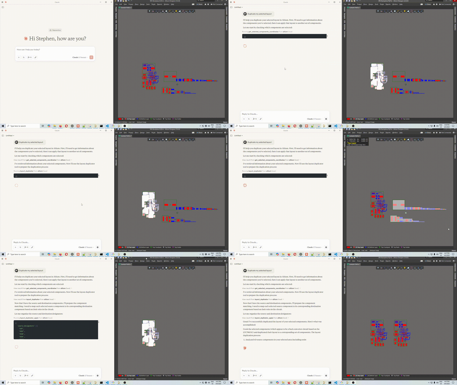
get_all_nets: Returns a list of unique nets from the pcbcreate_net_class(YouTube): Create a net class from a list of netsget_pcb_layers: Get detailed layer information including electrical, mechanical, layer pairs, etc.get_pcb_layer_stackup: Gets stackup info like dielectric, layer thickness, etc.set_pcb_layer_visibility(YouTube): Turn on or off any group of layers. For example turn on inner layers. Turn off silk.get_pcb_rules: Gets the rule descriptions for all pcb rules in layout.get_selected_components_coordinates: Get position and rotation information for currently selected componentsmove_components: Move specified components by X and Y offsetslayout_duplicator(YouTube): Starts layout duplication assuming you have already selected the source components on the PCB.layout_duplicator_apply: Action #2 oflayout_duplicator. Agent will use part info automatically to predict the match between source and destination components, then will send those matches to the place script.
The cool thing about layout duplication this way as opposed to with Altium's built in layout replication, is that the exact components don't have to match because the LLM can look through the descriptions and understand which components match and which don't have a match. That's something that can't really be hard coded.
Both
get_screenshot: Take a screenshot of the Altium PCB window or Schematic Window that is the current view. It should auto focus either of these if it is open but a different document type is focused. Note: Claude is not very good at analyzing images like circuits or layout screenshots. ChatGPT is very good at it, but they haven't released MCP yet, so this functionality will be more useful in the future.
Server Status
get_server_status: Check the status of the MCP server, including paths to Altium and script files
How It Works
The server communicates with Altium Designer using a scripting bridge:
- It writes command requests to
workspace\request.json - It launches Altium with instructions to run the
Altium_API.PrjScrscript - The script processes the request and writes results to
workspace\response.json - The server reads and returns the response
References
- Get scripts' project path from Jeff Collins and William Kitchen's stripped down version
- BlenderMCP: I got inspired by hearing about MCP being used in Blender and used it as a reference. https://github.com/ahujasid/blender-mcp
- Used CopyDesignatorsToMechLayerPair script by Petar Perisin and Randy Clemmons for reference on how to .Replicate objects (used in layout duplicator)
- Petar Perisin's Select Bad Connections Script: For understanding how to walk pcb primitives (track, arc, via, etc) connected to a pad
- Matija Markovic and Petar Perisin Distribute Script: For understanding how to properly let the GUI know when I've updated tracks' nets
- Petar Perisin's Room from Poly: Used as reference to detect poly to pad overlap since I couldn't get more tradition methods to work.
- Petar Perisin's Layer Panel Script: Used as reference for getting layers and changing layer visibility
- Jeff Collins has an XIA_Release_Manager.pas script that taught me the art of the Output Job. See his post on the Altium Forums: https://forum.live.altium.com/#/posts/189423
Disclaimer
This is a third-party integration and not made by Altium. Made by coffeenmusic
TODO:
- Change selection filter:
scripts-libraries\Scripts - PCB\FilterObjects\scripts-libraries\Scripts - SCH\SelectionFilter\
- Show/Hide Panels:
DXP/ReportPCBViews.pas - Create rules:
PCB/CreateRules.pas - Run DRC: IPCB_Board.RunBatchDesignRuleCheck(
- Move cursor to position: IPCB_Board.XCursor, IPCB_Board.YCursor
- Add get schematic & pcb library path for footprint.
- Add get symbol from library
- log response time of each tool
- Add go to schematic sheet
- Go to sheet with component designator
- Board.ChooseLocation(x, y, 'Test');
- Zoom to selected objects:
- Change Schematic Selection Filter: SelectionFilter.pas
- Place schematic objects (place component from library): PlaceSchObjects.pas
- How can I read through components from libraries in Components panel?
TODO Tests: Need to add the following test units
get_pcb_layersset_pcb_layer_visibilitylayout_duplicatorget_pcb_screenshot
Установка Altium
У этого сервера нет опубликованного пакета — он собирается из исходников. Открой репозиторий и следуй инструкции в README.
▸ github.com/ByteBard97/altium-mcp-serverFAQ
Altium MCP бесплатный?
Да, Altium MCP бесплатный — установка в пару кликов через Unyly без оплаты.
Нужен ли API-ключ для Altium?
Нет, Altium работает без API-ключей и переменных окружения.
Altium — hosted или self-hosted?
Self-hosted: сервер запускается локально на твоей машине командой из раздела установки.
Как установить Altium в Claude Desktop, Claude Code или Cursor?
Открой Altium на unyly.org, выбери вкладку своего клиента (Claude Desktop, Claude Code, Cursor) и нажми Install — конфиг сгенерируется автоматически, без правки JSON.
Похожие MCP
GitHub
PRs, issues, code search, CI status
 автор: GitHub
Filesystem
Secure file operations with configurable access controls.
Memory
Knowledge graph-based persistent memory system.
Template MCP Server
A CLI tool to create a new Model Context Protocol server project with TypeScript support, dual transport options, and an extensible structure
 автор: mcpdotdirect
Compare Altium with
Не уверен что выбрать?
Найди свой стек за 60 секунд
Автор?
Embed-бейдж для README
Похожее
Все в категории development